Monday, October 21, 2013

What now?!

Lizard dance celebration (Photo credit)
This will be the final blog post in this series as I have now graduated as a MSc in engineering design and applied mechanics. Wooop! In this post I will report on the work carried out between handing in and presenting my thesis. I will summarise the feedback that I received and then list some practical advice for those interested. 


Heat pipe with luer and end cap

Final work

In the last 10 days before presenting, I felt it would be worthwhile to try and charge/seal the prototypes and then thermally test them. However, I was never able to evacuate the heat pipes correctly or seal them after the charging attempt. It was pre-mature going ahead with prototyping and it would have been better stopping sooner and writing up on the results, even if it meant that the heat pipes were not created.


Testing set up (HP highlighted in red)

However, regardless of the seal, I still wanted to go ahead with the testing to see what kind of heat conductivity I might get out of the prototypes (stubborn). I set up the apparatus as shown on the right, with the heat pipe clamped gently in the heater (the evaporator end) and a fan set up at the condenser side (to focus the flow, I made a cardboard box element to focus the flow - left image). It was necessary to deflect the forced cool air from the hot end and so a guard (aluminium foil) was placed between both ends. As the HP was not filled correctly, the applied heat only increased the temperature at the hot end and there was an accumulation of heat there. After reaching around 90 °C, it was removed and it was observed that the Si seemed to warp. The results were not conclusive but due to time limits I took some readings using a laser infra-red thermometer which was awkward due to the experimental set up. This was a good example of how not to run an experiment...


Feedback

Although the literature review and presentation was good, I lacked enough analysis and structure relating to the experimental results. I should have focused on the wick structure element and characterised it more thoroughly, perhaps by comparing it to other wick structures currently available. I didn't persuade the examiner that by further investing effort in a lizard inspired wick surface, a more effective and economic solution could be found for the cooling problem. But the biggest rookie mistake I made was that I did not summarise clearly the results of the hypothesis in the summary. These were expensive mistakes...


Final words of advice

Here are some final words of advice which might help you out: 
  • Create a deadline for when to stop creating new data, finish experiments, develop prototypes etc. Focus on the analysis of the work you have done to that date as you will be more thorough and scientific in your analysis. I would suggest stopping 3 weeks before you hand in the thesis. I found this hard to do...
  • Present your supervisor with bullet point lists of what you have accomplished every week in a paragraph. Less is more for these busy people!
  • Order parts and components early in the process and make sure you have funds (ask your supervisor). However, I would suggest only ordering parts when you know they will work...or at least are nearly sure they will!
  • You have to hand in the thesis in hard copy and electronic. I think the number of hard copies vary depending on the department/supervisor and number of examiners.
  • The presentation can last 30 minutes. After this, there is a round of questions which lasts approx. 45 minutes. There can be questions from the examiners (two in my case, one being my supervisor) and I also had a question from a member of the audience. I don't think that inviting guests is of any benefit to your presentation but then again, maybe you might feel more like a rock star. You are then asked to leave where they will make the judgement.
  • I had too much to say during the presentation and although I practised it with a friend beforehand, I felt I was rushing through it. The feedback on the slide show was good but I think that I should have reduced the amount of content and chatter. You can find the presentation below (Prezi of course):


Thank you/mange tak!

Thanks for reading and keep in touch with me through LinkedIn: 
dk.linkedin.com/in/bryanoregan/ or visit my website: www.suiledesign.com - always interested in collaborating on projects when I can. Good luck! Bryan.

Tuesday, August 20, 2013

Charging and sealing the prototype before the big day

A selection of the FMHP prototypes
Last week I handed in my thesis one hour before setting off to Cork in Ireland for a family holiday. I now have to send in two hard copies to my supervisor from Ireland. My defence is on Thursday 12 September but before then, I have to get the prototypes working. I return back to Copenhagen on Monday 10 September which leaves very little time to fix some big issues including:
  1. Charging and sealing the flat micro heat pipe (FMHP)
  2. Setting up the equipment for testing the heat transfer capabilities of the FMHP and working out the overall thermal conductivity of the prototypes
  3. Organise the data and compare to literature 
  4. Putting together the presentation and other stuff that I hope to use for the defence.

Leak tests

I set up a simple leak test to check whether the glue had worked on the prototype FMHP. I set up a test as shown in the image below, sucking out the air, closing the valve and then dipping the end of the tube in water. Opening the valve allowed the water to be sucked through the tube, hence proof that a vacuum existed. However, there could be slow leaks, given time, would relieve the pressure - to be sure, I added an extra layer of sealant. 
 

Leak test set up (red areas show potential leak points)

Charging and sealing

Each prototype has an inlet consisting of PTFE tubing with 0.6 mm outer diameter. I am going to attempt to fill/charge the FMHP using a syringe vacuum technique. I will try to evacuate air from the FMHP, then use the internal vacuum in the FMHP to suck in a volume of fluid which should wet the wick section. Then I will crimp shut the PTFE tubing.

FMHP charging set up

The biggest headache thus far has been figuring out how to crimp the FMHP shut. I have tried different methods and tested the crimp by flushing air through and watching for bubbles in a water bath.

Needle inserted in PTFE tubing and crimped - FAIL.
So far I have tried three different crimping methods and they have all failed:
  1. Metal sleeve crimp (as in the last blog post) - this cracked the PTFE tubing and leaked
  2. Needle crimp - I inserted a steel needle into the PTFE tube (applying glue) and then crimped the steel. I tried a number of crimps, at different angles on the needle but it still leaked. Out of five attempts, one seemed to hold but there was still some air bubbles visible at the outlet. One small bubble seemed to just stick at the end of the needle and I am not sure why this happened.
  3. Tube bending - I tried to bend the tubing 180 ° and tie the tube in this position but it still leaked.
I am now looking at finding a Teflon sealed adaptor or something that will allow me to inject fluid and then pull out the syringe without losing vacuum pressure and/or fluid. Hopefully someone at DTU Nanotech can help with this.

Testing equipment

Once filled and sealed, I will have FMHP ready for testing. With testing, I will have to apply heat at one end of the FMHP over a small area and then measure the temperature at the other end in order to calculate the over all heat transfer. Practical considerations for the experimental set up will include:
  1. Heater with controllable hot plate that can preferably apply a controlled amount of heat to the Si side of the FMHP. This might involve creating a metal shim 1 cm² in area and surrounding it with insulating material so that heat is focused on a particular region (as in a CPU cooling situation). A thermal insulation paste will be needed to create good contact with the FMHP.
  2. Thermometers to read the temperatures at different points on the heat pipe. It will be necessary to glue the thermometers which means I need approx 6 per FMHP prototype - 2 at the hot end (evaporator), 2 at the centre (adiabatic region) and 2 at the cold end (condenser). They will have to be glued (i.e. one use only) so I will also need a conductive glue.
  3. Prof. Larsen suggested a water cooler at the cold end where the inlet and outlet water temperature can be measured (more thermometers). This will involve a structure design which will allow the end of the FMHP fit in securely and be water tight.
And this all depends on whether these prototypes:
a) Melt - PVC can start to soften at 100 °C so I have to keep the temperatures below that which is the case for CPUs which need a safe operating temperature of approx. 85 °C
b) Leak - Will the glue crack and let air in or will the tubing connections leak?
c) Crack under vacuum - Will the combination of heat and pressure crack the plastic? Are there hidden cracks in the Si from my disastrous labelling method (using a glass cutter on Silicon!)
d) WORK! 

Sunday, July 21, 2013

A quick update on lab work

The Polymic group have kindly allowed me to use their lab to carry out the heat pipe fabrication work. I have been running from the Polymic lab to the Danchip lab and then another lab at the Nanotech building looking for parts in order to create the prototypes and testing systems. I am trying to avoid ordering parts but it has been difficult sourcing the components I need. The literature I am reading is not very precise on what gauges should be used or the components and as these are unique prototypes, I have been doing a 'cut to fit' job.

Creating the prototype 


Last week I spent a lot of time trying to bond the container and Si section together using the silicon based adhesive. To be honest, I am really not sure the bond will hold because in order to prevent any glue from contaminating the wick, I tried to apply it partially to the surface. It was the clamped for approx. 24 hours where I then applied another layer. I will be doing leak tests this week so if they fail, I might have to open them up, remove the glue and give the parts a clean and glue with something else.


Clamped carefully with clothes pegs

On clamping with the clothes pegs, another Si wafer bit the dust. The clamping must have again agitated a fracture in the Si wafer after I scratched it with the glass cutter (Roman numerals with all those straight lines...a bad choice!).

Cracked prototype.

The tube system can also be seen above on the cracked prototype. It will be covered at the connections with sealant.

Contact angle tests

From the previous research, Simon had placed the Si wafer with micro structure in the Plasma chamber for a couple of minutes in order to create a silicon oxide layer on the surface, making it more superhydrophilic. I have done this for all of the specimens and have carried out some 'rate of rise' velocity tests on the specimens.

Oxygen plasma treatment of the wick structures.
Contact angle test of Si wick structure after plasma treatment. The drop spreads instantly (as opposed to the untreated specimen) which means the surface is fully wetted.

Crimping

I have tested a crimp system and perhaps I can get that to work. However, it will difficult crimping the tubing of the cotainer which needs to be under a vacuum. Once I source a vacuum sensor of some kind, I can test this set up for leaks.

Crimping the tubing

Next...

I have been also working on putting together all of the information into the chapters on concept development and heat fabrication. As time is ticking away, I am not sure whether I will get to the testing stage as there are still the huge tasks of leak testing, charging and sealing.

Wednesday, July 10, 2013

Roskilde and discos (on PVC)

A weekend volunteering at the Danish Corner at Roskilde has left me anti-pork and suffering from man-flu. But regardless, I got something done in the last 3 days. Tomorrow I hope to begin gluing the container together in preparation for filling and sealing. I hand in August 7. Yikes.

Wafer set up before cutting

Disco cutting

Today we finished cutting out the wick sections thanks to help from another Danchip employee, Majken Becker. The Disco saw danced through the silicon like M.J. doing the moon walk through butter. However, I lost a couple of sections due to some work I did on the pieces beforehand. In order to label the sections, I used a glass cutter to mark them with Roman numerals from I - V. Funny, I thought the Roman numerals would look better (classy) but the straight lines I scratched into the surface must have aligned with the crystals in the silicon and once sawing began, the crack propagated through the whole section. 3 out of 10 wick sections were lost in this way. AND while drying the wick sections after a dose in the ultrasonic bath (5 minute blast), I was drying them with an air gun and nearly lost another part after it blew out of my hands and hit the floor. Manflu.  


PVC plastic cover for heat pipe

PVC container sections

10 covers have been machined using a milling process. The material is PVC and was chosen because it was available and a quick calculation shows that it should be OK under pressures up to 2 bar with a wall thickness of 1 mm. A 1 mm diameter hole has been drilled in the centre for filling. I am not looking forward to filling and sealing. I will need to ensure that there are no other gases in the cavity and it needs to be sealed at the hole. The glue and hole need to hold when in operation.

Alicona image of cover wall showing debris

The milling process has left some debris around the edges which could contaminate the capillary structure. Even after 5 minutes in ultrasonic bath, there still appear to be leftovers from the milling so it might be necessary to sand these down. But then that could lead to further debris (finer debris) so I will probably go around the edge with a tweezers and pluck them off like hair from a brow.


Friday, June 28, 2013

Heat pipe cover materials

Yesterday was the 25th of June and according to my plan, I should have some heat pipes in my lap ready to be tested... Alas, due to busy schedules at DTU (some departments close for summer and people are taking vacation), it won't be until next week that I will be fabricating the different components including the etched silicon wafers (and cutting/cleaning) and the top covers. Still plenty to write about though and I have sent in a draft of chapter 4 relating to heat pipe technology (a literature review) to Torben. I will be adding a short chapter on my work methods and how I arranged my time, held meetings and put the project together. At this point, I have to consider the possibility (very real) that these heat pipes will not work and as my supervisor said, it is about the logical process and how you failed that is importa.... ah feck that! They better work!

Building the container

Yesterday I spoke with Jan F. Pedersen, who is the manager/foreman of the MEK production labs at building 427S at DTU. As before, he was very helpful and we discussed some issues regarding the milling of my parts. Three issues were clarified:

Milling depth - Depending on the time available, 10 covers will be fabricated. The vacuum cavity area of the heat pipe will remain at 1 mm high while the depth of the etch will vary. The milling drill head is 1 mm in diameter and had to be taken into account so that the covers would fit over the etched structures. A 1 mm hole will be drilled through the top of the container so that it can be filled.

Polyvinyl chloride (image credit)

Material - There are many different plastics available at the MEK building but it was necessary to go to the workshop to check out what was ready for milling. As discussed in the last blog the material should have high heat thermal conductivity and a low coefficient of thermal expansion. PVC was chosen as it is available but I think there could be problems with it.
  1. The thermal coefficient of expansion (E-6 mm/mm °C)  is 50.4 and for silicon is 3. Will the materials expand to a point which will create large stresses in the glue seal and rip the container?
  2. The thermal conductivity of PVC (W/m °C) is approx. 0.20 and 149 for silicon. At the cooler condenser end, it will be necessary to release the heat so this material will not be efficient at doing this. A suggestion from Jacob at the 3D Fab Lab at DTU seems the right choice: orientate the heat pipe such that the heat is released through the silicon side.

Sunday, June 16, 2013

Etching and micro-fab for this week

Summary

After a slight scare last week, a meeting at Danchip clarified some issues and made me realise that the error could be worked around. Again, I have had to make concessions with the design and pull back on some ideas that I have wanted to try out on the wick section to improve capillary action. With only a few days to go until I reach the experimental stage (Tuesday 25th June 2013), this week will be focused on etching the wafers, cutting them and machining the container cover. Then I will need to put it all together for the next stage: filling and sealing the container with working fluid before testing.

To etch...

I had a meeting with Karen Birkelund at Danchip which was very useful and allowed me to clarify what exactly I could achieve with etching considering the time limits and material I have to work with. She suggested that I could start from scratch and redesign the photomask (i.e. the layout of the lizard inspired wicks on the wafer) and create more workable structures. However this could take weeks. My desire has been to make do with what I have instead of spending more time and money (DTU's money!) on more material. However, in hindsight, after the time spent trying to figure out work arounds, it might have been more productive starting from scratch...c'est la vie!


...or what to etch


It has been confirmed that in fact, the 5 wafers that are in storage at Danchip have been treated with photoresist and were not etched. In the plasma etching process, although photoresist protects certain areas of the wafer, it is still actually being etched away, but at a slower rate to silicon. Depending on the depth of micro features, it can be necessary to use a thicker photoresist but hopefully in this case, I can avoid this process.

It has been an iterative process where the following etching concepts have been discussed and abandoned:

  • Depth variation laterally across the wick surface - this process has been not tested before at Danchip and it is feared that delicate equipment could be damaged. The application of Kapton tape to the wafer/photoresist surface could allow selective etching of certain areas but might also damage the photoresist when the tape is removed and prevent further etching.
  • Wet etch undercut - this would involve further training and although it could be an interesting result (mimicing the lizard more accurately), the creation of undercut channels would make mass manufacture using injection moulding very difficult as removal from the mould would destroy the structures. 
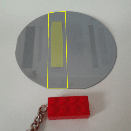
    Cut out (line) and wick area (shaded) 
    Cut out (line) and wick area (shaded)
  • Create heat pipe wicks from all wafer patterns - handling the wick pattern 'chips' will be difficult due to their small size and once made into a heat pipe container, creating a fill hole for charging and sealing would be very frustrating. Once etching is complete, there will  be 5 wafers of different etch depths varying from 30 to 150 μm. It has been decided that one wick 'chip' will be cut from each wafer so that a large enough surface surrounding the wick structure will be available to join the other container section (approx. 3 mm). The figure above show which sections will be used (shaded in red and yellow) and the cut lines are also shown. It will be necessary to cut out the 'chips' using a Disco cutting saw such that 5 chips will be available to create 5 heat pipe containers. They will then be cleaned and taken to the MEK micro fabrication department (building 427). Karen also suggested that 'blank' extras be made for practising the sealing process. Thanks Karen!

Container design 

Last week I spoke to Jan F. Pedersen who is the manager of the workshop at the MEK micro fabrication department (building 427) and was very helpful in his suggestions about the creation of the cover of the container and how it could be constructed. He said that it could be possible to machine a piece of plastic into a cover piece using a milling machine with a 1 mm milling tip (I need to confirm what he intends to use but hopefully I can get some hands on experience in this). It could then be glued to the silicon wafer wick section although this would need to be confirmed with the glue manufacturer (Loctite).


The following issues need to be clarified before machining begins:
  • Dimensions of container - although most of the dimensions will depend on the wick section area, the height of the container is very important as this will define the vapour section volume during operation. I still need to confirm the pressure drops across the container under different conditions and after reading that Benson et al. had designed flat heat pipes for a maximum pressure of 2 bar (!), my calculations could be well off (I have been thinking about pressures of up to 1 bar). The walls need to be thick enough so the container does not explode and rip off my face during testing (does anyone read this far?). The dimension of the fill hole will also be important but from the papers, 1 mm Ø could be OK but I need to clarify the filling and sealing operation also.
  • Material to be milled - the material will be a plastic and should be compatible with the working fluid (water). It should have a coefficient of thermal expansion which is similar to that of silicon so that when in operation, the silicon and cover will expand similarly. Cost is also important as it is hoped that both the cover and wick structure can be created in future using injection moulding so the cheaper the material, the better. The plastic must also have a high thermal conductivity such the heat is transferred through the material at the condenser end.
  • Bonding method - Jan suggested I look into the type of glue which could achieve a hermetically sealed connection under pressures of up to 2 bar, temperatures of up to 150 °C and also ensure that the glue does not break up over time (or during bonding) and contaminate the wick cavity. I emailed Loctite to enquire as to whether they have anything that might work. Otherwise, another bonding method will be used but as always, time is 'tite'...

Thursday, June 6, 2013

D'oh! Gettin' the etchin' wrong

I have always found it helpful to discuss projects with someone without a scientific background as they can ask questions which can bring about new ideas and thoughts about my work. Yesterday, I had one such conversation and realised that I had misunderstood something very important about the previous etching process from my last nanotechnology project.


Review of the photolithography and etching process

To understand the error I made regarding the etch patterns, I will try to summarise the photolithography and etching of SI wafers procedure below:

Cross sectional view of different layers. The clean wafer is placed in a hot oven for a short time so that a photo resist polymer layer can adhere better. The photo resist layer is spread over the surface evenly by spin coating.


Fig 2. Exposing the photoresist. The wafer is put in a machine where UV light is directed through a photo mask such that any part of the photo mask that does not block the UV light (like a theatre light gobo) and will allow it through to the wafer (yellow lines above). The UV light will alter the photo resist in these areas of the wafer.


Fig 3. Plasma (dry) etching of substrate. The wafer is then placed in a solution bath and the altered photo resist is removed in a similar way to how photography development is done. The wafer is then etched by plasma in the areas not protected by the photoresist.
Figure 4 & 5 below: I had assumed that the photo mask had worked such that the patterns were etched down into the wafer. However, the opposite happened and the result are patterns which are raised from the surface because everything except the pattern was exposed and developed. This means that the container design must be altered to take into account this different setup. D'oh!

Fig 4. WRONG! It was thought that the pattern would be etched into the wafer which was not the case (round silicon wafer shown in light grey).
Fig 5. CORRECT! The majority of the wafer was exposed and developed such that the plasma ate away at everything except the pattern, leaving it extruded from the surface (round silicon wafer shown in light grey).