Monday, October 21, 2013

What now?!

Lizard dance celebration (Photo credit)
This will be the final blog post in this series as I have now graduated as a MSc in engineering design and applied mechanics. Wooop! In this post I will report on the work carried out between handing in and presenting my thesis. I will summarise the feedback that I received and then list some practical advice for those interested. 


Heat pipe with luer and end cap

Final work

In the last 10 days before presenting, I felt it would be worthwhile to try and charge/seal the prototypes and then thermally test them. However, I was never able to evacuate the heat pipes correctly or seal them after the charging attempt. It was pre-mature going ahead with prototyping and it would have been better stopping sooner and writing up on the results, even if it meant that the heat pipes were not created.


Testing set up (HP highlighted in red)

However, regardless of the seal, I still wanted to go ahead with the testing to see what kind of heat conductivity I might get out of the prototypes (stubborn). I set up the apparatus as shown on the right, with the heat pipe clamped gently in the heater (the evaporator end) and a fan set up at the condenser side (to focus the flow, I made a cardboard box element to focus the flow - left image). It was necessary to deflect the forced cool air from the hot end and so a guard (aluminium foil) was placed between both ends. As the HP was not filled correctly, the applied heat only increased the temperature at the hot end and there was an accumulation of heat there. After reaching around 90 °C, it was removed and it was observed that the Si seemed to warp. The results were not conclusive but due to time limits I took some readings using a laser infra-red thermometer which was awkward due to the experimental set up. This was a good example of how not to run an experiment...


Feedback

Although the literature review and presentation was good, I lacked enough analysis and structure relating to the experimental results. I should have focused on the wick structure element and characterised it more thoroughly, perhaps by comparing it to other wick structures currently available. I didn't persuade the examiner that by further investing effort in a lizard inspired wick surface, a more effective and economic solution could be found for the cooling problem. But the biggest rookie mistake I made was that I did not summarise clearly the results of the hypothesis in the summary. These were expensive mistakes...


Final words of advice

Here are some final words of advice which might help you out: 
  • Create a deadline for when to stop creating new data, finish experiments, develop prototypes etc. Focus on the analysis of the work you have done to that date as you will be more thorough and scientific in your analysis. I would suggest stopping 3 weeks before you hand in the thesis. I found this hard to do...
  • Present your supervisor with bullet point lists of what you have accomplished every week in a paragraph. Less is more for these busy people!
  • Order parts and components early in the process and make sure you have funds (ask your supervisor). However, I would suggest only ordering parts when you know they will work...or at least are nearly sure they will!
  • You have to hand in the thesis in hard copy and electronic. I think the number of hard copies vary depending on the department/supervisor and number of examiners.
  • The presentation can last 30 minutes. After this, there is a round of questions which lasts approx. 45 minutes. There can be questions from the examiners (two in my case, one being my supervisor) and I also had a question from a member of the audience. I don't think that inviting guests is of any benefit to your presentation but then again, maybe you might feel more like a rock star. You are then asked to leave where they will make the judgement.
  • I had too much to say during the presentation and although I practised it with a friend beforehand, I felt I was rushing through it. The feedback on the slide show was good but I think that I should have reduced the amount of content and chatter. You can find the presentation below (Prezi of course):


Thank you/mange tak!

Thanks for reading and keep in touch with me through LinkedIn: 
dk.linkedin.com/in/bryanoregan/ or visit my website: www.suiledesign.com - always interested in collaborating on projects when I can. Good luck! Bryan.

Tuesday, August 20, 2013

Charging and sealing the prototype before the big day

A selection of the FMHP prototypes
Last week I handed in my thesis one hour before setting off to Cork in Ireland for a family holiday. I now have to send in two hard copies to my supervisor from Ireland. My defence is on Thursday 12 September but before then, I have to get the prototypes working. I return back to Copenhagen on Monday 10 September which leaves very little time to fix some big issues including:
  1. Charging and sealing the flat micro heat pipe (FMHP)
  2. Setting up the equipment for testing the heat transfer capabilities of the FMHP and working out the overall thermal conductivity of the prototypes
  3. Organise the data and compare to literature 
  4. Putting together the presentation and other stuff that I hope to use for the defence.

Leak tests

I set up a simple leak test to check whether the glue had worked on the prototype FMHP. I set up a test as shown in the image below, sucking out the air, closing the valve and then dipping the end of the tube in water. Opening the valve allowed the water to be sucked through the tube, hence proof that a vacuum existed. However, there could be slow leaks, given time, would relieve the pressure - to be sure, I added an extra layer of sealant. 
 

Leak test set up (red areas show potential leak points)

Charging and sealing

Each prototype has an inlet consisting of PTFE tubing with 0.6 mm outer diameter. I am going to attempt to fill/charge the FMHP using a syringe vacuum technique. I will try to evacuate air from the FMHP, then use the internal vacuum in the FMHP to suck in a volume of fluid which should wet the wick section. Then I will crimp shut the PTFE tubing.

FMHP charging set up

The biggest headache thus far has been figuring out how to crimp the FMHP shut. I have tried different methods and tested the crimp by flushing air through and watching for bubbles in a water bath.

Needle inserted in PTFE tubing and crimped - FAIL.
So far I have tried three different crimping methods and they have all failed:
  1. Metal sleeve crimp (as in the last blog post) - this cracked the PTFE tubing and leaked
  2. Needle crimp - I inserted a steel needle into the PTFE tube (applying glue) and then crimped the steel. I tried a number of crimps, at different angles on the needle but it still leaked. Out of five attempts, one seemed to hold but there was still some air bubbles visible at the outlet. One small bubble seemed to just stick at the end of the needle and I am not sure why this happened.
  3. Tube bending - I tried to bend the tubing 180 ° and tie the tube in this position but it still leaked.
I am now looking at finding a Teflon sealed adaptor or something that will allow me to inject fluid and then pull out the syringe without losing vacuum pressure and/or fluid. Hopefully someone at DTU Nanotech can help with this.

Testing equipment

Once filled and sealed, I will have FMHP ready for testing. With testing, I will have to apply heat at one end of the FMHP over a small area and then measure the temperature at the other end in order to calculate the over all heat transfer. Practical considerations for the experimental set up will include:
  1. Heater with controllable hot plate that can preferably apply a controlled amount of heat to the Si side of the FMHP. This might involve creating a metal shim 1 cm² in area and surrounding it with insulating material so that heat is focused on a particular region (as in a CPU cooling situation). A thermal insulation paste will be needed to create good contact with the FMHP.
  2. Thermometers to read the temperatures at different points on the heat pipe. It will be necessary to glue the thermometers which means I need approx 6 per FMHP prototype - 2 at the hot end (evaporator), 2 at the centre (adiabatic region) and 2 at the cold end (condenser). They will have to be glued (i.e. one use only) so I will also need a conductive glue.
  3. Prof. Larsen suggested a water cooler at the cold end where the inlet and outlet water temperature can be measured (more thermometers). This will involve a structure design which will allow the end of the FMHP fit in securely and be water tight.
And this all depends on whether these prototypes:
a) Melt - PVC can start to soften at 100 °C so I have to keep the temperatures below that which is the case for CPUs which need a safe operating temperature of approx. 85 °C
b) Leak - Will the glue crack and let air in or will the tubing connections leak?
c) Crack under vacuum - Will the combination of heat and pressure crack the plastic? Are there hidden cracks in the Si from my disastrous labelling method (using a glass cutter on Silicon!)
d) WORK! 

Sunday, July 21, 2013

A quick update on lab work

The Polymic group have kindly allowed me to use their lab to carry out the heat pipe fabrication work. I have been running from the Polymic lab to the Danchip lab and then another lab at the Nanotech building looking for parts in order to create the prototypes and testing systems. I am trying to avoid ordering parts but it has been difficult sourcing the components I need. The literature I am reading is not very precise on what gauges should be used or the components and as these are unique prototypes, I have been doing a 'cut to fit' job.

Creating the prototype 


Last week I spent a lot of time trying to bond the container and Si section together using the silicon based adhesive. To be honest, I am really not sure the bond will hold because in order to prevent any glue from contaminating the wick, I tried to apply it partially to the surface. It was the clamped for approx. 24 hours where I then applied another layer. I will be doing leak tests this week so if they fail, I might have to open them up, remove the glue and give the parts a clean and glue with something else.


Clamped carefully with clothes pegs

On clamping with the clothes pegs, another Si wafer bit the dust. The clamping must have again agitated a fracture in the Si wafer after I scratched it with the glass cutter (Roman numerals with all those straight lines...a bad choice!).

Cracked prototype.

The tube system can also be seen above on the cracked prototype. It will be covered at the connections with sealant.

Contact angle tests

From the previous research, Simon had placed the Si wafer with micro structure in the Plasma chamber for a couple of minutes in order to create a silicon oxide layer on the surface, making it more superhydrophilic. I have done this for all of the specimens and have carried out some 'rate of rise' velocity tests on the specimens.

Oxygen plasma treatment of the wick structures.
Contact angle test of Si wick structure after plasma treatment. The drop spreads instantly (as opposed to the untreated specimen) which means the surface is fully wetted.

Crimping

I have tested a crimp system and perhaps I can get that to work. However, it will difficult crimping the tubing of the cotainer which needs to be under a vacuum. Once I source a vacuum sensor of some kind, I can test this set up for leaks.

Crimping the tubing

Next...

I have been also working on putting together all of the information into the chapters on concept development and heat fabrication. As time is ticking away, I am not sure whether I will get to the testing stage as there are still the huge tasks of leak testing, charging and sealing.

Wednesday, July 10, 2013

Roskilde and discos (on PVC)

A weekend volunteering at the Danish Corner at Roskilde has left me anti-pork and suffering from man-flu. But regardless, I got something done in the last 3 days. Tomorrow I hope to begin gluing the container together in preparation for filling and sealing. I hand in August 7. Yikes.

Wafer set up before cutting

Disco cutting

Today we finished cutting out the wick sections thanks to help from another Danchip employee, Majken Becker. The Disco saw danced through the silicon like M.J. doing the moon walk through butter. However, I lost a couple of sections due to some work I did on the pieces beforehand. In order to label the sections, I used a glass cutter to mark them with Roman numerals from I - V. Funny, I thought the Roman numerals would look better (classy) but the straight lines I scratched into the surface must have aligned with the crystals in the silicon and once sawing began, the crack propagated through the whole section. 3 out of 10 wick sections were lost in this way. AND while drying the wick sections after a dose in the ultrasonic bath (5 minute blast), I was drying them with an air gun and nearly lost another part after it blew out of my hands and hit the floor. Manflu.  


PVC plastic cover for heat pipe

PVC container sections

10 covers have been machined using a milling process. The material is PVC and was chosen because it was available and a quick calculation shows that it should be OK under pressures up to 2 bar with a wall thickness of 1 mm. A 1 mm diameter hole has been drilled in the centre for filling. I am not looking forward to filling and sealing. I will need to ensure that there are no other gases in the cavity and it needs to be sealed at the hole. The glue and hole need to hold when in operation.

Alicona image of cover wall showing debris

The milling process has left some debris around the edges which could contaminate the capillary structure. Even after 5 minutes in ultrasonic bath, there still appear to be leftovers from the milling so it might be necessary to sand these down. But then that could lead to further debris (finer debris) so I will probably go around the edge with a tweezers and pluck them off like hair from a brow.


Friday, June 28, 2013

Heat pipe cover materials

Yesterday was the 25th of June and according to my plan, I should have some heat pipes in my lap ready to be tested... Alas, due to busy schedules at DTU (some departments close for summer and people are taking vacation), it won't be until next week that I will be fabricating the different components including the etched silicon wafers (and cutting/cleaning) and the top covers. Still plenty to write about though and I have sent in a draft of chapter 4 relating to heat pipe technology (a literature review) to Torben. I will be adding a short chapter on my work methods and how I arranged my time, held meetings and put the project together. At this point, I have to consider the possibility (very real) that these heat pipes will not work and as my supervisor said, it is about the logical process and how you failed that is importa.... ah feck that! They better work!

Building the container

Yesterday I spoke with Jan F. Pedersen, who is the manager/foreman of the MEK production labs at building 427S at DTU. As before, he was very helpful and we discussed some issues regarding the milling of my parts. Three issues were clarified:

Milling depth - Depending on the time available, 10 covers will be fabricated. The vacuum cavity area of the heat pipe will remain at 1 mm high while the depth of the etch will vary. The milling drill head is 1 mm in diameter and had to be taken into account so that the covers would fit over the etched structures. A 1 mm hole will be drilled through the top of the container so that it can be filled.

Polyvinyl chloride (image credit)

Material - There are many different plastics available at the MEK building but it was necessary to go to the workshop to check out what was ready for milling. As discussed in the last blog the material should have high heat thermal conductivity and a low coefficient of thermal expansion. PVC was chosen as it is available but I think there could be problems with it.
  1. The thermal coefficient of expansion (E-6 mm/mm °C)  is 50.4 and for silicon is 3. Will the materials expand to a point which will create large stresses in the glue seal and rip the container?
  2. The thermal conductivity of PVC (W/m °C) is approx. 0.20 and 149 for silicon. At the cooler condenser end, it will be necessary to release the heat so this material will not be efficient at doing this. A suggestion from Jacob at the 3D Fab Lab at DTU seems the right choice: orientate the heat pipe such that the heat is released through the silicon side.

Sunday, June 16, 2013

Etching and micro-fab for this week

Summary

After a slight scare last week, a meeting at Danchip clarified some issues and made me realise that the error could be worked around. Again, I have had to make concessions with the design and pull back on some ideas that I have wanted to try out on the wick section to improve capillary action. With only a few days to go until I reach the experimental stage (Tuesday 25th June 2013), this week will be focused on etching the wafers, cutting them and machining the container cover. Then I will need to put it all together for the next stage: filling and sealing the container with working fluid before testing.

To etch...

I had a meeting with Karen Birkelund at Danchip which was very useful and allowed me to clarify what exactly I could achieve with etching considering the time limits and material I have to work with. She suggested that I could start from scratch and redesign the photomask (i.e. the layout of the lizard inspired wicks on the wafer) and create more workable structures. However this could take weeks. My desire has been to make do with what I have instead of spending more time and money (DTU's money!) on more material. However, in hindsight, after the time spent trying to figure out work arounds, it might have been more productive starting from scratch...c'est la vie!


...or what to etch


It has been confirmed that in fact, the 5 wafers that are in storage at Danchip have been treated with photoresist and were not etched. In the plasma etching process, although photoresist protects certain areas of the wafer, it is still actually being etched away, but at a slower rate to silicon. Depending on the depth of micro features, it can be necessary to use a thicker photoresist but hopefully in this case, I can avoid this process.

It has been an iterative process where the following etching concepts have been discussed and abandoned:

  • Depth variation laterally across the wick surface - this process has been not tested before at Danchip and it is feared that delicate equipment could be damaged. The application of Kapton tape to the wafer/photoresist surface could allow selective etching of certain areas but might also damage the photoresist when the tape is removed and prevent further etching.
  • Wet etch undercut - this would involve further training and although it could be an interesting result (mimicing the lizard more accurately), the creation of undercut channels would make mass manufacture using injection moulding very difficult as removal from the mould would destroy the structures. 
    Cut out (line) and wick area (shaded) 
    Cut out (line) and wick area (shaded)
  • Create heat pipe wicks from all wafer patterns - handling the wick pattern 'chips' will be difficult due to their small size and once made into a heat pipe container, creating a fill hole for charging and sealing would be very frustrating. Once etching is complete, there will  be 5 wafers of different etch depths varying from 30 to 150 μm. It has been decided that one wick 'chip' will be cut from each wafer so that a large enough surface surrounding the wick structure will be available to join the other container section (approx. 3 mm). The figure above show which sections will be used (shaded in red and yellow) and the cut lines are also shown. It will be necessary to cut out the 'chips' using a Disco cutting saw such that 5 chips will be available to create 5 heat pipe containers. They will then be cleaned and taken to the MEK micro fabrication department (building 427). Karen also suggested that 'blank' extras be made for practising the sealing process. Thanks Karen!

Container design 

Last week I spoke to Jan F. Pedersen who is the manager of the workshop at the MEK micro fabrication department (building 427) and was very helpful in his suggestions about the creation of the cover of the container and how it could be constructed. He said that it could be possible to machine a piece of plastic into a cover piece using a milling machine with a 1 mm milling tip (I need to confirm what he intends to use but hopefully I can get some hands on experience in this). It could then be glued to the silicon wafer wick section although this would need to be confirmed with the glue manufacturer (Loctite).


The following issues need to be clarified before machining begins:
  • Dimensions of container - although most of the dimensions will depend on the wick section area, the height of the container is very important as this will define the vapour section volume during operation. I still need to confirm the pressure drops across the container under different conditions and after reading that Benson et al. had designed flat heat pipes for a maximum pressure of 2 bar (!), my calculations could be well off (I have been thinking about pressures of up to 1 bar). The walls need to be thick enough so the container does not explode and rip off my face during testing (does anyone read this far?). The dimension of the fill hole will also be important but from the papers, 1 mm Ø could be OK but I need to clarify the filling and sealing operation also.
  • Material to be milled - the material will be a plastic and should be compatible with the working fluid (water). It should have a coefficient of thermal expansion which is similar to that of silicon so that when in operation, the silicon and cover will expand similarly. Cost is also important as it is hoped that both the cover and wick structure can be created in future using injection moulding so the cheaper the material, the better. The plastic must also have a high thermal conductivity such the heat is transferred through the material at the condenser end.
  • Bonding method - Jan suggested I look into the type of glue which could achieve a hermetically sealed connection under pressures of up to 2 bar, temperatures of up to 150 °C and also ensure that the glue does not break up over time (or during bonding) and contaminate the wick cavity. I emailed Loctite to enquire as to whether they have anything that might work. Otherwise, another bonding method will be used but as always, time is 'tite'...

Thursday, June 6, 2013

D'oh! Gettin' the etchin' wrong

I have always found it helpful to discuss projects with someone without a scientific background as they can ask questions which can bring about new ideas and thoughts about my work. Yesterday, I had one such conversation and realised that I had misunderstood something very important about the previous etching process from my last nanotechnology project.


Review of the photolithography and etching process

To understand the error I made regarding the etch patterns, I will try to summarise the photolithography and etching of SI wafers procedure below:

Cross sectional view of different layers. The clean wafer is placed in a hot oven for a short time so that a photo resist polymer layer can adhere better. The photo resist layer is spread over the surface evenly by spin coating.


Fig 2. Exposing the photoresist. The wafer is put in a machine where UV light is directed through a photo mask such that any part of the photo mask that does not block the UV light (like a theatre light gobo) and will allow it through to the wafer (yellow lines above). The UV light will alter the photo resist in these areas of the wafer.


Fig 3. Plasma (dry) etching of substrate. The wafer is then placed in a solution bath and the altered photo resist is removed in a similar way to how photography development is done. The wafer is then etched by plasma in the areas not protected by the photoresist.
Figure 4 & 5 below: I had assumed that the photo mask had worked such that the patterns were etched down into the wafer. However, the opposite happened and the result are patterns which are raised from the surface because everything except the pattern was exposed and developed. This means that the container design must be altered to take into account this different setup. D'oh!

Fig 4. WRONG! It was thought that the pattern would be etched into the wafer which was not the case (round silicon wafer shown in light grey).
Fig 5. CORRECT! The majority of the wafer was exposed and developed such that the plasma ate away at everything except the pattern, leaving it extruded from the surface (round silicon wafer shown in light grey).

Saturday, June 1, 2013

Getting stuck at Danchip

Sticky stuff
At our last meeting, myself and Torben discussed deadlines, holidays and defence day (D-Day). My hand in deadline is the first week in August after which I will go home to Ireland for a few weeks. Then in mid-September I will defend the project. At this point it would be beneficial to begin writing the chapter list and begin putting together the content. Again, I juggle between the benefits of LaTex and Word.


Danchip visit

The good news is that Simon and Rafael have some time to assist me on this project. Last week I took a visit to Danchip and put on the CSI gear (plus new beard mask) and entered the sombre world of the Danchip clean rooms to find my wafers. The Silicon (SI) wafers (5 in all) and photomask were still there which was a relief. However, each wafer was etched! I really do not remember etching all the wafers as we were initially to test one first as per my last report, and then proceed with the others. So this was not expected...

Problem?

At first, this seemed like something which could limit the project but in hindsight, it really did not matter that the wafers were etched with 30 μm deep structures. The photo resist should still be in place as the wafers were not (hopefully) treated after the etching process and according to Simon, the wafers can be re-etched to change the surface characteristics. I have created a process request for Danchip (sent to training @ Danchip) including the following:


As the liquid thins at the hot, evaporator end, high capillary pumping action is needed and a possible improvement in the wick surface might be by having smaller channels at the hot end. Kapton tape can protect certain areas of the pattern from the plasma etch

Wet etched undercut
  1. Dry etching  - 2 wafers will be plasma etched such that the structures depth increase laterally across the wick (image below),
  2. Wet etching - 2 wafers will be etched so that an undercut can be created under the photomask,
  3. Cutting - cut out the wick sections and spacers using a Disco saw (there is a clean spare wafer and one that I have taken from the lab which would need to be cleaned before being brought back into the lab),
  4. Bonding the wick sections and spacers together to form a heat pipe container.

Executing these processes in a timely manner will depend on Danchip's schedule. During my last etching session, one of the Danchip staff mentioned that I could perhaps have someone carry out the processes rather than train/learn how to use new equipment myself. Also, I am also not sure whether these processes will be accepted at the lab (this is why they request process plans in case someone tries something that could damage equipment). I will also enquire as to whether the laser cutter at DTU's Innovatorium could be useful for cutting the SI (although from experience, there might be residue left behind which could prevent the bonding process from working).

So hopefully next week, I can start making these heat pipes. Then, I will try to make them work...

Sunday, May 26, 2013

Blood squirting lizards!

Researching lizards is fun. In a previous blog post, I discussed the Phrynosoma cornutum, P. coronatum, and P. solare, which are commonly known (albeit inaccurately) as Horned Toads. With their interesting water harvesting skin (the inspiration for my thesis), they also have an intriguing defence mechanism...

Friday, May 24, 2013

Get it done! Concept fab, experiments and thesis plan

Wow...10 weeks until thesis hand in...how did that happen?! I was a little distracted last week as we had a very exciting folk music night at the apartment which went down very well. But since then, I have been trying to move things forward and can report some progress.

Wick patterns on silicon wafer surface

Creating the concepts

I have sent an update on my thesis progress to Rafael Taboryski and Simon Tylsgaard Larsen at POLYMIC. During my previous work with them, we fabricated some micro structures on silicon wafers using photolithography and etching equipment at the Danchip National Center for Micro- and Nanofabrication clean rooms. The idea was to test how these structures (inspired by the skin of a lizard) could be scaled and how this scaling affected the hydrophilic and capillary action characteristics of the surface. Some qualitative rate of rise tests were carried out but due to time constraints it was not possible to show how varying channel width could improve these properties.

Cut SI patterns before anode bonding

In my proposed plan, I have tried to simplify the method for producing flat micro heat pipes that could be fabricated on the remaining SI wafers which have been prepared for etching. I just hope they have not been discarded! There are 4 wafers left so by etching these with different pattern characteristics (varying etch depth, channel width, surface treatments perhaps), variations of wick patterns could be produced. By cutting these patterns out, 2 of the same design could be bonded together using an anode bonding process to create a heat pipe container. Then the container would need to be filled with the working fluid (DI water) and sealed so that any other gases are removed. If 4 wafers were etched, it might be possible to create 12 different heat pipe containers with varying wicks. However, all of this work will depend on whether Rafael and Simon have time to assist and Danchip facilities are accessible over the coming weeks.

Hot plates with control box on right

Experimental testing

To get things moving with the experimentation stage, I decided to contact Giuliano Bissacco at the MEK department at DTU to discuss heating equipment for use in testing of the flat micro heat pipes. He has worked with cooling problems before and was very helpful in our meeting today. He showed me a hot plate/thermal test rig which could be used for testing. An aluminium support (good conductor of heat) might be needed to hold the heat pipe containers where the surface area is chosen such that a controllable heat flux (watt per area) can be applied to the evaporator end of the heat pipe. However, we discussed using the plates themselves to grip the heat pipe container gently and a piece of insulating material (e.g. Rockwool) could be placed on the top side to ensure that most of the heat input comes from the bottom plate (as in microprocessor setups).  

Thesis structure

Finally, I have put together a visual overview of the report structure. You can find the presentation here which shows an overview of the different elements that I will try to cover: objectives, report layout and milestones as per the problem statement. I am considering using LaTex but just need to get off my ass and get going with it!

<If anyone knows how to centre an iframe in Blogger, please leave a comment>


Wednesday, May 15, 2013

Bringing in the professionals

This morning I had a meeting with Masoud Rokni who is an expert in heat transfer and associate professor at DTU Mechanical Engineering. I had some questions regarding the lizard inspired wick and how to define it for my analysis on the maximum capillary action that could be achieved by such a structure. Some clarifications were made regarding:
  • How to define the cross sectional area of the heat pipe system (in this case, rectangular) in order to calculate the heat transfer coefficient, h (W/(m²K) of the system which can then be used to calculate the value of heat dissipation, Q (W or J/s) for the total system.
  • Which values to be chosen for calculating the different pressure drops across the heat pipe wick (due to gravity, vapour and liquid) including vapour viscosity, μvap (kg/s·m) which can be found in heat transfer tables varies little with pressure, and the latent heat of vaporisation, hfg (kJ/kg) which is very much dependent on pressure changes (values found in thermodynamic tables).
Circular channels with over hanging section
Most importantly, he clarified how I should define the effective pore radius! Previously I had been looking at the lizard wick as an open surface with hexagonal micro posts. I was simplifying the design to make it easier but in doing so, complicated the problem. I failed to recognise that due to the overhanging part of the post, the wick could be viewed as an almost closed section covering the circular channels. So the effective pore radius can be taken has half the channel width.

It was also noted again that the cross sectional area of the channel is very important in calculating the maximum capillary action achievable. By decreasing the size of the channels, the capillary action will increase. 

In future iterations of the design, varying the cross sectional area of the channels across the wick could take into account the different stages of wetting of the working fluid  (in this case deionized water). At the evaporator end where fluid is heated, the channels will be more tightly packed to take into account that wetting will be less than at the condenser end. However, I need to have a concept first before thinking these details. Thanks Masoud.  

Friday, May 10, 2013

Taking aim and the LaTex/Word war!

Defining the hypothesis

SEM-image of Moloch horridus (image credit)
After weeks of research, I am now trying to focus on the exact hypothesis I wish to prove for this thesis so the following is a repeat of past posts but trys to focus things. I wish to show that inspiration found in nature (biomimicry, biomimetics or bio-inspired design) can be used to improve on a current technology. In this case the inspiration is stemming from a selection of lizards and toads who have evolved integuments (skin and scales) which allow them to harvest water passively in arid conditions where sources of hydration are limited. This survival strategy implements capillary action forces in the lizard's integument which provides the mechanism for transporting water passively across the lizard's skin and hydrates the animal by absorption and in some cases actually directs the fluid to the lizard's mouth.

It is believed that a similar geometry to that of the lizard's integument can be applied to the problem of overheating in micro electronics such as microprocessors which need to be cooled to safe operating temperatures of approximately 80 °C. Heat pipes are being developed for this task and a critical element within these systems is the wick - a porous micro structure which, through capillary force action, directs working fluid from the condenser section to the evaporator passively. The wick section must ensure that enough fluid is available at the evaporator so that the fluid can be heated to a vapour (taking in heat from the CPU) and then travel away from the heat source. The vapour then reaches the condenser again cools to a fluid, releasing it's latent heat. This cooled fluid then travels thought the wick to the evaporator and the cycle continues. By implementing a lizard inspired wick design, I hope to show that heat transfer can be improved and that the heat pipe system can work more effectively than current designs. From research, the following reasons indicate that pursuing this concept could be worthwhile:
  • Heat transfer within a heat pipe is dependent on the wick structure which can increase surface area such that the working fluid and wick interact optimally in order to transfer heat. The lizard's integument shows a characteristic arrangement which could improve on current wick designs and improve heat transfer from the hot source to the working fluid.
  • The one directional flow of working fluid in some cooling concepts (e.g. micro channels and liquid cooling plates) can limit heat transfer. The hexagonally packed polygonal micro structures found in the lizard's integument allows two directional fluid flow. This means that there is less likelihood for channel blockage as fluid can traverse across different flow paths.
This thesis will be an example of a bottom up design where we start with an interesting concept in nature and apply it to an application. It will be necessary to show a systematic design approach including how the inspiration was found and why this certain application was chosen. As I grapple with the complexities of heat pipe systems, I will attempt to relate this concept to others and with some luck, provide an improvement in their design.       

LaTex versus Word: a war at DTU!

Latex versus Word (image credit)

Speaking to fellow MSc students, I have come to realise that there are many using LaTex to create their thesis report. Although our discussions have never turned to violence, their passion for LaTex reminds me of old school Mac vs Windows debates. I have always used Word for reports and only heard about LaTex in my third semester here at DTU. For the following reasons, I will not be using LaTex for this report:
  1. The time needed to figure out LaTex will probably take at least 24 hours for what I want to do. Even with Word's problems regarding formatting, jumping images, referencing etc., I think that I will spend less than 24 hours fixing up the paper before hand in.
  2. It does not seem to be a requirement for this project although I have heard of some supervisors insisting on using LaTex.
  3. I don't like the look of LaTex documents.
So I will persevere with Word and grow a tougher integument as 'LaTex-heads' lecture me on how amazing the programme is. ;)  

Tuesday, May 7, 2013

Wickedly tricky

At my last meeting with my supervisor on Tuesday 30 April, I presented my attempt at trying to quantify capillary action and the overall function of a heat pipe cooling system by implementing a wick structure in the model which was inspired by a lizard's integument (skin and scales). This proved very difficult! Since then, my mission has been to prove that this type of geometry would be an improvement on current wick designs and therefore move forward to a new phase of development in my thesis. Otherwise, I might have to drop this particular issue and move onto to some other area where this inspiration could be used more effectively.

Heat pipes and wick structures

Copper heat pipe wick section (image credit)
As mentioned previously, a heat pipe is a passive system which is used to cool things such as electronic components. If you opened your laptop, you would find a heat pipe system which consists of the hot section (evaporator), the wick section (the flat copper piping) and condenser section where a cooling fan is located. Inside this sealed container is a working fluid (e.g. DI water or methanol) which is cooked at the hot side and evaporates. This vapour flows to the cooler region where it condenses to a fluid again (two phase change) releasing it's latent heat. It is this release of latent heat that makes the heat pipe so effective. The condensed fluid then fills the wick and is dragged back to the evaporator section where the process begins again. Research is being carried out on the wick section and the creation of micro post arrays with various cross sections (circular, square, pie shaped etc.) and are well adapted to electronics cooling because they allow the working fluid to move two-dimensionally across the wick (rather than micro channels which only allow axial flow for example) and can allow multiple components to be cooled with one system. The image above shows a common circular cross section heat pipe. Flat plate heat pipes (FPHP) are similar but they provide less area for the vapour and fluid to flow (increase in pressure drop) which decreases the overall effectiveness of the heat pipe. Researchers believe that by optimising the wick structure, heat transfer of over 150 W/cm² can be achieved. It looks like the trick is in the wick...

Dimensioning the wick structure

Currently, my main focus is on the wick section of the heat pipe which is critical to the successful operation of the system. The geometry of the wick section must provide enough back pressure to ensure that there is enough supply of fluid to the evaporator section. This capillary limit, ΔPc is dependent on two main variables which I have been trying to get my head around:
  • The effective pore radius, reff - The porosity is dependent on the size of the voids in the wick and is the ratio of void volume to the total volume of the wick. This value affects the permeability, K or how well the fluid flows through the wick. Increasing the size of the voids can improve the permeability of the wick but can decrease the capillary limit (capillary action improves with decrease in channel/void size) so the balance has to be right. 
  • The surface tension, σl/v - at the liquid vapour interface. Having a higher surface tension means that the wick is wetted more effectively.  
The formula relating the two is:
∆Pcap = l/v
reff

This equation brought up the following queries (and many more) that needed clarification:
  1. The surface tension of the fluid will change across the surface of the wick as it comes from the condenser and travels towards the evaporator. However, a paper by Wallin shows the assumption that the surface tension is constant throughout the wick axially along the pipe.
  2. I really am finding it difficult to find a paper that describes visually the 'effective pore radius'. Is this related to the channel length? Or to the radius of a cylindrical post? If the pore is not circular, how can I adapt the formula without messing up the result?
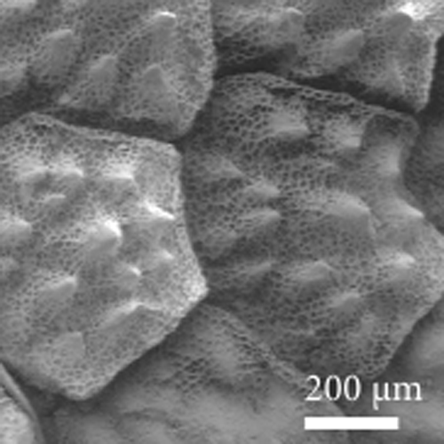
Can this wick surface beat others?
I felt it was time to call in the big guns and contacted Torben for some contacts at DTU who might be able to help with this set up and clarify some details about heat pipe wicks. However, after sending some emails, I realised that I was perhaps again complicating the task of proving that the lizard structure was a worthwhile investment. The surface is very effective at transporting water through capillary action so it can be seen as a superhydrophilic surface. I was overlooking the literature on superhydrophilic surfaces which I reviewed in my last project. These papers have many examples of micro post structures and might provide a similar geometry or method of describing this polygonally shaped design. For my meeting tomorrow, Wednesday 8 May, it was back to the drawing board.

Sunday, April 28, 2013

A new contender: the horned frog or horny toad or horned toad...

Over the last week, I have mostly been focusing on further research of heat pipe technology and have been attempting (with difficulty) to quantify the potential action that could result in using lizard inspired micro structured surfaces in a passive heat pipe cooler. I have again read an interesting paper on the anatomy of the Thorny Devil and discovered that I had overlooked some other lizards with interesting features that promote water harvesting.


Enter the Phrynosoma cornutum!

Texas Horned lizard (image credit)

Initially in my previous Nanotechnology project, I had reviewed the strategy database on AskNature.org and came across the Thorny Devil. I found an interesting paper entitled 'Moisture harvesting and water transport through specialized micro-structures on the integument of lizards'. It has many interesting images and observations of different lizards including the 'Phrynosoma cornutum' which is also known as the Texas Horned lizard and is a member of the "horned frog" family. Supposedly they have a similar rounded body and blunt snout as some frogs. The research paper shows that this horned lizard shows further enhancement of the undercut micro structure and the image shown below (skin cross section) is actually more pronounced than that of the Thorny Devil. With that, it turns out that the Thorny Devil lizard is not in the same family as the Horned lizard and although they show similarities in their structure, they are supposedly an example of convergent evolution where two different species have evolved similar anatomies to achieve the same endpoint e.g. eating lots of ants. To protect themselves, these lizards will put their head between their front legs and a part of their neck will then resemble a false head with horns, scaring or poking predators if they come too close. It just shows again that there are many various strategies in nature, even within specie groups and families. Having a holistic overview is difficult to achieve. 

Section of Texas Horned devil (image credit)
 
Whether the Thorny Devil is in fact a lesser opponent for design inspiration will depend on whether semi circular channels inspired by the Texas Horned lizard will improve capillary action under the stringent conditions necessary in heat pipe containers. The addition of this design feature (the undercut channels) would seem like a logical iteration from the simplified hexagonal posts fabricated in previous concept work. The next post will hopefully show some quantitative estimations of the capillary action due to this geometry in a passive heat pipe setup.

Wednesday, April 17, 2013

Can't see the wood for the trees

Yesterday I had my first 'milestone' presentation with my supervisor, Torben Lenau. As part of the problem statement, it was necessary to set out a time line of activities which included milestone presentations where reached goals are presented, discussions are had, changes are made and the supervisor can keep up with my activities. It can also mean that the direction of the thesis can change...

Micro cooling electronics
CPU pre-cooler install (image credit)

I have been researching micro cooling technologies used in electronics, specifically CPU (computational processing unit) devices. Newer devices are getting smaller and more powerful but the draw back is that they are giving out more heat. Heat flux is the rate of heat energy transfer through a surface and used as a measure of CPU performance. A CPU such as a Pentium 4 processor (used in home PCs and laptops) can emit heats of up to 115 W/cm² (where W is Watts or Joules per second). There are devices producing up to 150 W/cm² in computers and in other applications (hybrid cars, defence systems) researchers are looking at heat fluxes of up to 1000 W/cm²! Researchers like Issam Mudawar at Purdue university and Meilin Liu at Georgia Intitute of Technology (and many others) have been trying to solve the problem of over heating electronics in domestic, industrial, aviation and space systems.

Over the last 5 weeks, I have come to realise that the issue of cooling electronics is a huge area. There are a number of different techniques used including heat sinks (passive and fan assisted), liquid cooling, refrigeration, thermoelectric cooling, single and two phase changing liquids (using latent heat effects) and all of these are huge subjects in themselves. Many research papers have been written regarding the optimisation of geometries, fluid flow models, heat transfer and thermodynamics. Some observers believe it is now time to implement innovative and novel solutions which can solve the problem rather than focusing on theory, which can be time consuming in a world where technology is moving at such a fast pace. I felt that by applying some biomimetic inspired elements to a certain cooling process, there might be some benefits. This was a wrong approach.


Focus
Silicon wafer with lizard inspired geometry

The reason I wanted to write a thesis on 'Thorny Devil lizard inspired cooling' was to implement my previous findings in a cooling solution principal. At the milestone, my supervisor reminded me of this. Although my research was interesting and worthwhile for a holistic overview of micro cooling technology, it was taking on too much. It was necessary to focus on the interesting capillary action that takes place on this lizard inspired surface and how this passive action could be used in a cooling solution. It does not have to be limited to CPU cooling but a concept needs to be proven to work. For our next meeting (Tuesday 30 April), my tasks are to quantify:
  1. How to use capillary action to increase surface area (and promote heat transfer) and guide fluid around a system to improve cooling.
  2. How much heat are we talking about and how efficient a system like this could be.

Friday, April 12, 2013

It's on!

Some admin stuff...
I don't know this man - Image credit

On Friday April 5, I received an email saying that I have been officially registered in the DTU system for my thesis project. Not only that, I have been registered 1 month behind so the official date is actually March 1! I will be taking 32.5 ECTS so that means my thesis 'contract' deadline is Thursday August 15 2013. It was necessary to write out a problem statement outlying what I wanted to achieve, my learning objectives and a time line. According to friends, the problem statement can change up to a month after submission but for now the title is 'Thorny Devil lizard inspired cooling' and my supervisor is Prof. Torben Lenau.

The problem statement can be found here. It was tricky writing out the problem statement in order to get the scope correct, especially this early in the project. Defining the learning objectives needed wording like 'After the project the student is capable of …' so that the examiner can judge whether I have learned anything. My supervisor provided some useful information on how to complete a problem statement: Learning Objectives for Master's thesis at DTU Management Engineering. It was also advised to relate the statement to the competences listed in my MSc description.   


Wednesday, April 3, 2013

Hello from Copenhagen

Welcome to my MSc blog. This is my 4th and final semester at the Technical University of Denmark where I have been studying as a masters student in engineering design and applied mechanics. Over the next 5-6 months I will be researching, conceptualising, analysing and hopefully creating a new micro cooler device for the cooling of electronics. 
Thorny Devil lizard (image credit)

This blog is a follow up to my previous one that I kept last semester and followed an interesting 3 week course that I was doing on the creation of a micro surface inspired by the Thorny Devil lizard. If you wish to review the blog, you can find it here.

I learned a lot from that blog, mainly that I should never keep one again! It was very time consuming but I think it is a nice way to keep things together; my thoughts, concepts, interesting finds and perhaps, who knows, someone might find it interesting. This time, however, I will try to keep it more structured and to the point (less waffle, as I am inclined to do), with at least an entry per week summarising my work done. Apart from focusing on the main content and activities of the thesis, I will also describe any organisational activities or bureaucratic issues which have influenced progress. Hopefully, this blog will act as some sort of guide for future students (on how not to do things perhaps!). Ultimately, I want to expand my knowledge on the interesting issue of cooling micro electronics and bring some new thoughts and insights to the world.

Thank you,
Bryan.
www.suiledesign.com