
Now located in London. Some thoughts on engineering design, biomimicry, open innovation, business and anything really.
Sunday, May 26, 2013
Blood squirting lizards!
Friday, May 24, 2013
Get it done! Concept fab, experiments and thesis plan
Wow...10 weeks until thesis hand in...how did that happen?! I was a little distracted last week as we had a very exciting folk music night at the apartment which went down very well. But since then, I have been trying to move things forward and can report some progress.
 |
| Wick patterns on silicon wafer surface |
Creating the concepts
I have sent an update on my thesis progress to Rafael Taboryski and Simon Tylsgaard Larsen at POLYMIC. During my previous work with them, we fabricated some micro structures on silicon wafers using photolithography and etching equipment at the Danchip National Center for Micro- and Nanofabrication clean rooms. The idea was to test how these structures (inspired by the skin of a lizard) could be scaled and how this scaling affected the hydrophilic and capillary action characteristics of the surface. Some qualitative rate of rise tests were carried out but due to time constraints it was not possible to show how varying channel width could improve these properties.
In my proposed plan, I have tried to simplify the method for producing flat micro heat pipes that could be fabricated on the remaining SI wafers which have been prepared for etching. I just hope they have not been discarded! There are 4 wafers left so by etching these with different pattern characteristics (varying etch depth, channel width, surface treatments perhaps), variations of wick patterns could be produced. By cutting these patterns out, 2 of the same design could be bonded together using an anode bonding process to create a heat pipe container. Then the container would need to be filled with the working fluid (DI water) and sealed so that any other gases are removed. If 4 wafers were etched, it might be possible to create 12 different heat pipe containers with varying wicks. However, all of this work will depend on whether Rafael and Simon have time to assist and Danchip facilities are accessible over the coming weeks.
 |
| Cut SI patterns before anode bonding |
In my proposed plan, I have tried to simplify the method for producing flat micro heat pipes that could be fabricated on the remaining SI wafers which have been prepared for etching. I just hope they have not been discarded! There are 4 wafers left so by etching these with different pattern characteristics (varying etch depth, channel width, surface treatments perhaps), variations of wick patterns could be produced. By cutting these patterns out, 2 of the same design could be bonded together using an anode bonding process to create a heat pipe container. Then the container would need to be filled with the working fluid (DI water) and sealed so that any other gases are removed. If 4 wafers were etched, it might be possible to create 12 different heat pipe containers with varying wicks. However, all of this work will depend on whether Rafael and Simon have time to assist and Danchip facilities are accessible over the coming weeks.
 |
| Hot plates with control box on right |
Experimental testing
To get things moving with the experimentation stage, I decided to contact Giuliano Bissacco at the MEK department at DTU to discuss heating equipment for use in testing of the flat micro heat pipes. He has worked with cooling problems before and was very helpful in our meeting today. He showed me a hot plate/thermal test rig which could be used for testing. An aluminium support (good conductor of heat) might be needed to hold the heat pipe containers where the surface area is chosen such that a controllable heat flux (watt per area) can be applied to the evaporator end of the heat pipe. However, we discussed using the plates themselves to grip the heat pipe container gently and a piece of insulating material (e.g. Rockwool) could be placed on the top side to ensure that most of the heat input comes from the bottom plate (as in microprocessor setups).
<If anyone knows how to centre an iframe in Blogger, please leave a comment>
Thesis structure
Finally, I have put together a visual overview of the report structure. You can find the presentation here which shows an overview of the different elements that I will try to cover: objectives, report layout and milestones as per the problem statement. I am considering using LaTex but just need to get off my ass and get going with it!<If anyone knows how to centre an iframe in Blogger, please leave a comment>
Wednesday, May 15, 2013
Bringing in the professionals
This morning I had a meeting with Masoud Rokni who is an expert in heat transfer and associate professor at DTU Mechanical Engineering. I had some questions regarding the lizard inspired wick and how to define it for my analysis on the maximum capillary action that could be achieved by such a structure. Some clarifications were made regarding:
- How to define the cross sectional area of the heat pipe system (in this case, rectangular) in order to calculate the heat transfer coefficient, h (W/(m²K) of the system which can then be used to calculate the value of heat dissipation, Q (W or J/s) for the total system.
- Which values to be chosen for calculating the different pressure drops across the heat pipe wick (due to gravity, vapour and liquid) including vapour viscosity, μvap (kg/s·m) which can be found in heat transfer tables varies little with pressure, and the latent heat of vaporisation, hfg (kJ/kg) which is very much dependent on pressure changes (values found in thermodynamic tables).
 |
| Circular channels with over hanging section |
Most importantly, he clarified how I should define the effective pore radius! Previously I had been looking at the lizard wick as an open surface with hexagonal micro posts. I was simplifying the design to make it easier but in doing so, complicated the problem. I failed to recognise that due to the overhanging part of the post, the wick could be viewed as an almost closed section covering the circular channels. So the effective pore radius can be taken has half the channel width.
It was also noted again that the cross sectional area of the channel is very important in calculating the maximum capillary action achievable. By decreasing the size of the channels, the capillary action will increase.
In future iterations of the design, varying the cross sectional area of the channels across the wick could take into account the different stages of wetting of the working fluid (in this case deionized water). At the evaporator end where fluid is heated, the channels will be more tightly packed to take into account that wetting will be less than at the condenser end. However, I need to have a concept first before thinking these details. Thanks Masoud.
Friday, May 10, 2013
Taking aim and the LaTex/Word war!
Defining the hypothesis
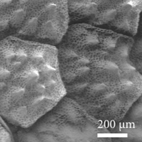 |
| SEM-image of Moloch horridus (image credit) |
It is believed that a similar geometry to that of the lizard's integument can be applied to the problem of overheating in micro electronics such as microprocessors which need to be cooled to safe operating temperatures of approximately 80 °C. Heat pipes are being developed for this task and a critical element within these systems is the wick - a porous micro structure which, through capillary force action, directs working fluid from the condenser section to the evaporator passively. The wick section must ensure that enough fluid is available at the evaporator so that the fluid can be heated to a vapour (taking in heat from the CPU) and then travel away from the heat source. The vapour then reaches the condenser again cools to a fluid, releasing it's latent heat. This cooled fluid then travels thought the wick to the evaporator and the cycle continues. By implementing a lizard inspired wick design, I hope to show that heat transfer can be improved and that the heat pipe system can work more effectively than current designs. From research, the following reasons indicate that pursuing this concept could be worthwhile:
- Heat transfer within a heat pipe is dependent on the wick structure which can increase surface area such that the working fluid and wick interact optimally in order to transfer heat. The lizard's integument shows a characteristic arrangement which could improve on current wick designs and improve heat transfer from the hot source to the working fluid.
- The one directional flow of working fluid in some cooling concepts (e.g. micro channels and liquid cooling plates) can limit heat transfer. The hexagonally packed polygonal micro structures found in the lizard's integument allows two directional fluid flow. This means that there is less likelihood for channel blockage as fluid can traverse across different flow paths.
LaTex versus Word: a war at DTU!
 |
| Latex versus Word (image credit) |
Speaking to fellow MSc students, I have come to realise that there are many using LaTex to create their thesis report. Although our discussions have never turned to violence, their passion for LaTex reminds me of old school Mac vs Windows debates. I have always used Word for reports and only heard about LaTex in my third semester here at DTU. For the following reasons, I will not be using LaTex for this report:
- The time needed to figure out LaTex will probably take at least 24 hours for what I want to do. Even with Word's problems regarding formatting, jumping images, referencing etc., I think that I will spend less than 24 hours fixing up the paper before hand in.
- It does not seem to be a requirement for this project although I have heard of some supervisors insisting on using LaTex.
- I don't like the look of LaTex documents.
Tuesday, May 7, 2013
Wickedly tricky
At my last meeting with my supervisor on Tuesday 30 April, I presented my attempt at trying to quantify capillary action and the overall function of a heat pipe cooling system by implementing a wick structure in the model which was inspired by a lizard's integument (skin and scales). This proved very difficult! Since then, my mission has been to prove that this type of geometry would be an improvement on current wick designs and therefore move forward to a new phase of development in my thesis. Otherwise, I might have to drop this particular issue and move onto to some other area where this inspiration could be used more effectively.
As mentioned previously, a heat pipe is a passive system which is used to cool things such as electronic components. If you opened your laptop, you would find a heat pipe system
which consists of the hot section (evaporator), the wick section (the
flat copper piping) and condenser section where a cooling fan is
located. Inside this sealed container is a working fluid (e.g. DI water
or methanol) which is cooked at the hot side and evaporates. This vapour
flows to the cooler region where it condenses to a fluid again (two
phase change) releasing it's latent heat. It is this release of latent heat that makes the heat pipe so effective. The condensed fluid then fills the wick and is dragged back to the evaporator section where the process begins again. Research is being carried out on the wick section and the creation of micro post arrays with various cross sections (circular, square, pie shaped etc.) and are well adapted to electronics cooling because they allow the working fluid to move two-dimensionally across the wick (rather than micro channels which only allow axial flow for example) and can allow multiple components to be cooled with one system. The image above shows a common circular cross section heat pipe. Flat plate heat pipes (FPHP) are similar but they provide less area for the vapour and fluid to flow (increase in pressure drop) which decreases the overall effectiveness of the heat pipe. Researchers believe that by optimising the wick structure, heat transfer of over 150 W/cm² can be achieved. It looks like the trick is in the wick...
I felt it was time to call in the big guns and contacted Torben for some contacts at DTU who might be able to help with this set up and clarify some details about heat pipe wicks.
However, after sending some emails, I realised that I was perhaps again
complicating the task of proving that the lizard structure was a
worthwhile investment. The surface is very effective at transporting
water through capillary action so it can be seen as a superhydrophilic surface. I
was overlooking the literature on superhydrophilic surfaces which I
reviewed in my last project. These papers have many examples of micro post structures and might provide a similar geometry or method of describing this polygonally shaped design. For my meeting tomorrow, Wednesday 8 May, it was back to the drawing board.
Heat pipes and wick structures
 |
| Copper heat pipe wick section (image credit) |
Dimensioning the wick structure
Currently, my main focus is on the wick section of the heat pipe which is critical to the successful operation of the system. The geometry of the wick section must provide enough back pressure to ensure that there is enough supply of fluid to the evaporator section. This capillary limit, ΔPc is dependent on two main variables which I have been trying to get my head around:- The effective pore radius, reff - The porosity is dependent on the size of the voids in the wick and is the ratio of void volume to the total volume of the wick. This value affects the permeability, K or how well the fluid flows through the wick. Increasing the size of the voids can improve the permeability of the wick but can decrease the capillary limit (capillary action improves with decrease in channel/void size) so the balance has to be right.
- The surface tension, σl/v - at the liquid vapour interface. Having a higher surface tension means that the wick is wetted more effectively.
| ∆Pcap = | 2σl/v |
| reff |
This equation brought up the following queries (and many more) that needed clarification:
- The surface tension of the fluid will change across the surface of the wick as it comes from the condenser and travels towards the evaporator. However, a paper by Wallin shows the assumption that the surface tension is constant throughout the wick axially along the pipe.
- I really am finding it difficult to find a paper that describes visually the 'effective pore radius'. Is this related to the channel length? Or to the radius of a cylindrical post? If the pore is not circular, how can I adapt the formula without messing up the result?
 |
| Can this wick surface beat others? |
Subscribe to:
Posts (Atom)